BABY LISA PROJECT
WARNING : This page documents and only documents the building of , “Baby Lisa.” , the information here is not meant to be a how to guide , propane is dangerous and I am not qualified to teach anyone how to use propane. What you see here may not work or may be dangerous. Do your own research should you decide to build anything like this and take all necessary safety precautions.
REMEMBER : It’s what you know for certain that can kill you !
INTRODUCTION
The ,”Baby Lisa Project.” , started in March of 2022. Originally, the goal was to build a small gas kiln but it soon was evident the kiln was actually a sculpture and I envision all the art produced by it a part of that sculpture.
A sculpture that produces itself.
I should add , it’s all highly experimental , my experience with clay very limited , besides grade school experiences in the 70’s making elephants for my aunt , I did not touch clay again till 2019 and later in 2020.
The clay I made in 2020 sat for two years in a bone dry state as I pondered buying a kiln. It was in March of 2022, I was moved to make a gas powered kiln that would become ,”Baby Lisa.”.
This page documents it’s design , construction and operation and will document its very first firing for better or for worse.
It’s all really a big unknown. The kiln could fire and end in total destruction taking the art in it to its doom or produce some authentic art.
One way or another it will be an adventure , the largest undertaking for a single project in the history of the art gallery.
***
THE SCHEDULE
The kiln is scheduled to be fired on October 15, 2022. The burner system is now complete , I am currently gathering parts to build the kiln and will start it’s construction during September of 2022.
Here is a recap of what has transpired so far on the project.
***
THE BURNER SYSTEM
The first stage of the project was to select a burner to power the kiln and to assemble it with all the valves, piping , fittings and other structures needed to safely operate and use the burner productively to power the kiln.
All of this makes up the, Burner System.
This resulted in a lot of research online , not only to understand the theory of burner design but to locate and aquire the parts needed to build the burner system.
Needless to say perhaps , Google , YouTube and Amazon were very useful in helping find everything needed to build the burner system and the kiln project.
Many ceramicist and others were very informative in making of this project and they will be recognized later on this page.
***
The burner system needs to deliver enough power to not only heat the clay to the desired temperature but it has to be supplied in a controlled manner. The clay must rise in temperature over time and not simply reach a given temperature.
The goal of this project is to slowly reach about 1950 F in about 7 or 8 hours and then to slowly cool the kiln back to ambient temperature.
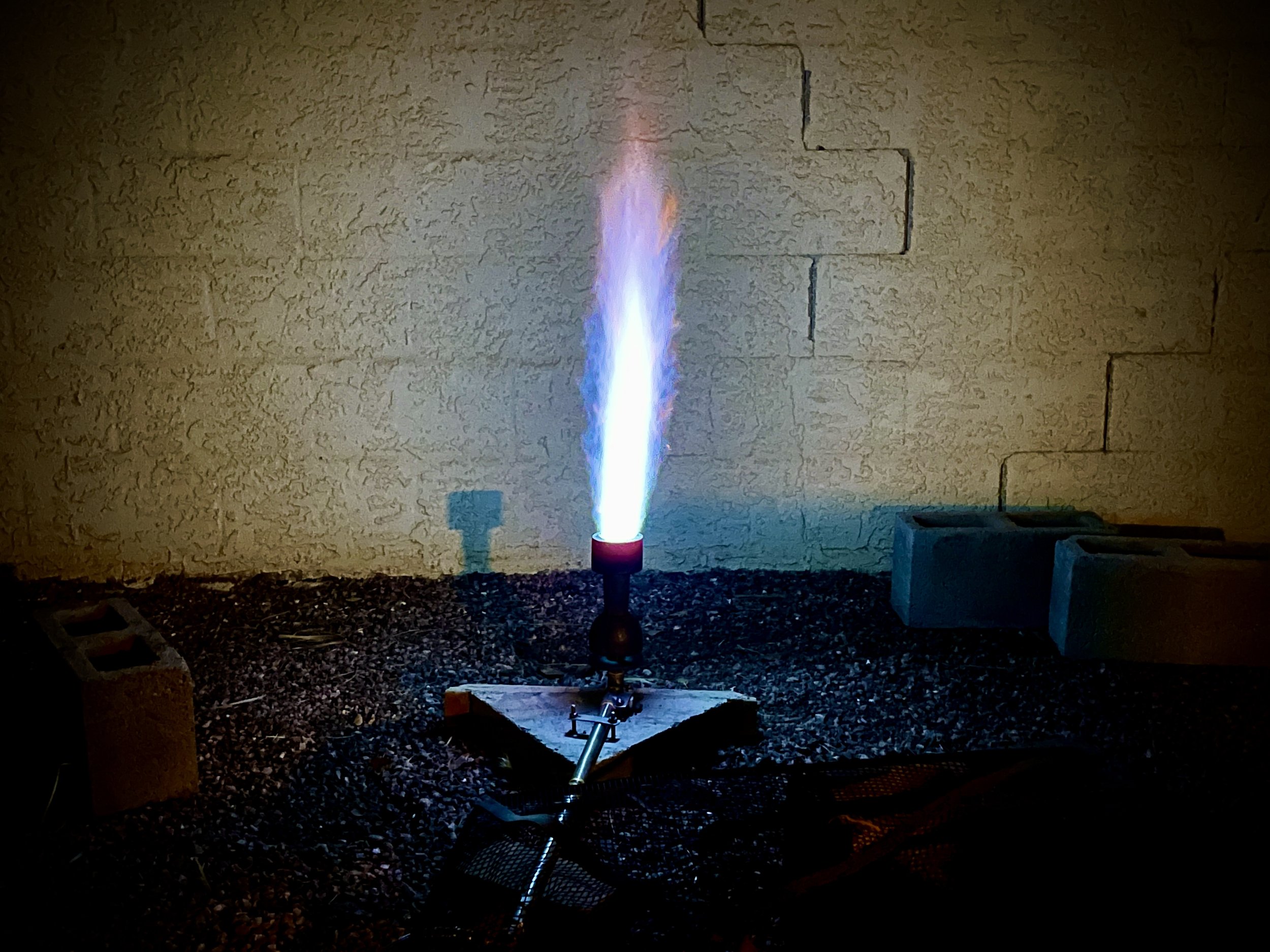
A key component in this regard was a brass needle valve, it has so far demonstrated the ability to adjust the burner flame from a very soft orange candle flame and in small increments to a roaring large blue flame of at least 26 inches tall.
Below Image : HongBoW Instrument Needle Valve ( 3/8 inch Brass ).

This needle valve in line with a pressure gauge gives the ability to quantitatively monitor and regulate the gas pressure to the MR 100 burner.
This is separate regulation apart from the high pressure regulator and gauge attached to the propane cylinder. Used to set the overall line pressure.

Above Image ; Needle valve and inline pressure gauge.
Below Image ; High Pressure Regulator and pressure gauge mounted to 40 pound propane tank. Used to set line pressure.

Below Image ; High energy flame and low flame at very low pressure, attainable solely by operation of needle valve.

The needle valve is part of the gas assembly unit , which as mentioned contains a needle valve in line with a pressure gauge and followed by a 1/2 inch ball valve.
This ball valve is the fastest way to shut off power / gas to the kiln and still be a safe distance from the kiln. It’s function is, an emergency shut off valve.

Above Image ; Gas Assembly , right to left , needle valve , pressure gauge , emergency shut off valve ( Ball Valve. ).
The Control Panel
The components of the burner system are connected via flexible hose. This would make it awkward to operate the various valves as the torque of turning the valves on and off would not encounter any resistance , the valves would more then likely twist.
To solve this a sturdy control panel was constructed from 1/4 “ plywood framed with 2x3 inch boards. This in turn was bolted to a heavy cinder block filled with concrete.
The gas assembly was in turn mounted to the control panel via u bolts. This provided for a very secure and stable place to operate the valves and monitor kiln performance.
The control panel also contains the digital temperature meter and timer and is equipped with a light in the advent of kiln operation during dark periods and contains a clipboard to record data.

Above Image ; Mounting Block for control panel.

Above Image ; Control Panel bolted to mounting block supported by cinder blocks.
The Burner Assembly
The burner assembly consist of the MR 100 Venturi Burner , the burner mounting block and kiln ignition valve.

Above Image ; Burner Mounting Block.
The burner mounting block keeps the burner in place during the opening and closing of the kiln ignition valve.
While the ignition system is very simplistic , keeping the kiln ignition valve ( ball valve ) at arms length from the burner , and securely mounted to the burner block , facilitates slowly opening the ignition valve with one hand , while simultaneously holding a flame over the burner with the other hand.
Below Image ; Burner assembly attached to 3/8 inch braided stainless steel gas hose.


Above Image ; Close up of MR 100 Venturi Burner , showing flame deflector below ( disc structure ) and the main body , also mounting brackets and plumbing.

Above Image ; Main burner body removed showing brass #38 propane nozzle. The flame deflector is visible below the nozzle , it rotates on a threaded fitting and can open and close the air passage into the burner.

Above Image ; Looking down into the burner , note brass nozzle. The burner is 3 inches wide , at full power makes a flame close to 4 inches.

Above Image ; Kiln Ignition Valve , 1/2 inch ball valve.

Above Image ; Control panel with 40 pound propane tank in the distance. The actual system will use two 40 pound tanks connected together.
THE CLAY
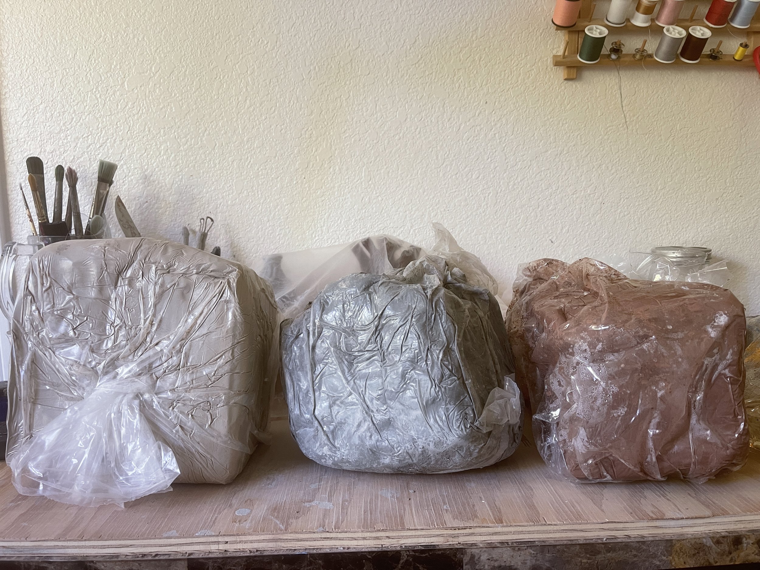
Three types of clay will be used during the first firing.
Below Image ; from left to right. A raku clay with sand added , a grey clay with grog and a red clay.
All these clays are specified to bisque fire at approximately Cone 04, about 1950 F.
Clays shrink and undergo stresses while being heated and changing to ceramics.
I will use these different clays to see if any of them does better in the kiln. I anticipate the kiln will provide a rocky ride up to Cone 04.
Another Burner Test #3
Baby Lisa Born on October 29 th 2022. Part 1 Kiln features and Bisque firing first time firing kiln.
Detailed discussion to follow soon.